| Machining | Pulley Assembly | Hardware Install | Sensor Wiring | Software Setup |
Machining
Here is the procedure to machine your own pulley, if you choose to do it yourself. The overall process is the same for both aluminum and steel pulleys. If it looks to intimidating you can always send it in for us to complete for you.
Tools you'll need:
9" Lathe - Or a friend with one..
8" calipers
Dial test indicator
2 x Mag Base for X and Y
2" dial indicator (optional for cut depth)
1" dial indicator
1-2-3 blocks
Pencil / Pen
Some paper
About an hour

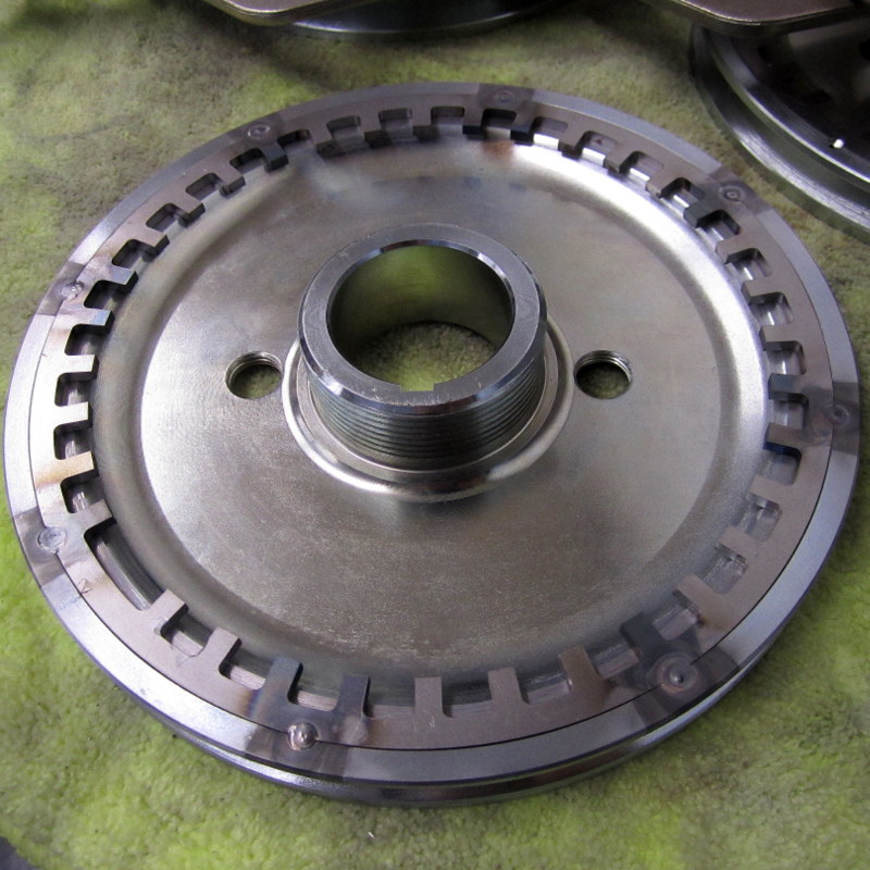
Shown is a process to machine your crank pulley to accept a hidden crank trigger wheel. |

You will need have your pulley with trigger wheel, a note pad, pencil and some 8" calipers. |

First and foremost, once you have fixed the the pulley onto your chuck DO NOT leave the chuck key in the chuck. The photo is just an illustration for the process. |

Once your pulley is secure and you have removed the chuck key you can now start to zero in your pulley as shown with a dial test indicator with a resolution of at least .0005". Here is an inexpensive one if you are looking to buy one - https://amzn.to/2YMUbuT |

You will want to rotate the pulley manually and find the low spot. Here we are about .002" from true. Softly tap the face of the pulley to bring this to zero. With premium pulleys it is easy to achieve a tolerance of +/- .0005". Some pulley types will only dial into +/- .0015", don't worry it isn't the end of the world. Continue on. |

This pulley came out to just under .0005" from hi to lo, that is a good pulley! |

Next I will touch the the tooling to the rear pulley face and zero my dial indicator (poor mans DRO) |

I then use a 1-2-3 block to find the outside edge and use this as a tooling reference. |

You can do this before mounted, but it's time to write down your pulley OD. After measuring twice I found 6.7515" to be the largest. |

Now measure your trigger wheel. Start with the depth moving to a 3 point measure of the OD. We will average those as a starting point. |

Now all the is done, crunch the numbers. Averaging my 3 outside measurements I came up with a OD of 6.377". 6.751" - 6.377" = .374" / 2 = .187" from the OD of the pulley. |

Moving the head toward the pulley center a little over .187" (.190" for come fudge factor) I then set my 2nd dial indicator to zero. |

Taking small passes start counter boring your pulley watching the dials to make sure you stay within your limits. |

Don't forget to measure as you go, it's easy to take material away but not to replace it. I'm just under the target of 6.377" so lets fit it up. |

Glad I stopped early for a test fit. It slides in with a slight press fit. That is exactly what we want. Now we can check depth and make the final passes. |

With a couple more measures and a very light clean up pass we are at our depth goal, -0.120". |

One last check with the trigger wheel in place all is looking good! |

Here is the finished product ready to remove and head to the drill press for drilling and tapping or welding. This has taken about 45 minutes to complete. |
Pulley Assembly
Click on your pulley type below, or scroll down to the appropriate section:
Aluminum Pulley
Tools you'll need:
Drill Press
#4-40 Tap and #43 Pilot Drill
7/64" Drill Bit
#4 Countersink
Blue Loctite
Sharpie
30-45 minutes
|
Step #1 Once you get your pulley back from the machine shop you will want to mark the missing tooth location. 42.5° BBDC - 7" Pulley
|

Step #2 Using a 90 degree angle straight edge, transfer the line down the side and to the backside of the pulley. |

Step #3 Mark the center of your missing tooth as a reference. |

Step #4 Transfer your mark from the front of your pulley to the back side and get the trigger wheel ready to insert into the counter bore that has been machined in. |

Step #5 The trigger wheel should now be pressed into the pulley with a very slight press fit. It should not rotate freely. At this time verify the Key-way on the pulley and the missing tooth are on the right half of the pulley. If the missing tooth is on the lower left it's incorrect.
|

Step #6 With your #4 pilot drill work your way around the pulley drilling the holes through into the pulley groove.
|

Step #7 Use caution to not drill through into the other side of the pulley grove. |

Step #8 Next we are using the countersink bit to sink in the machine screws. They can't stick up otherwise they will hit the sensor. Only countersink enough to make the fasteners flush or slightly recessed. The hole has been countersunk just enough for the #4-40 Machine screw to sit flush.
|

Step #9 Now we need to use the 7/64" drill bit and drill only throught he remaining steel so the screw slided through freely. View next Picture. |

Step #10 With the holes prepped and the trigger wheel clearanced, we are now ready to tap the hole. Your pulley should now look like this in at least one location to prevent the trigger wheel from rotating while tapping the rest of the holes. |

Step #11 I recommend using some tapping fluid to prevent the tap from seizing. Slow and steady wins this step. Make sure your tap is kept vertical so your screw goes in straight. |

Step #12 Once the first hole is tapped, install a screw and complete the remaining holes in the same manner. You may need to file the screw in the pulley groove once installed. |

Step #13 After they are all complete, pull out the screws and trigger wheel. Clean away all the cutting fluid. Reinstall the trigger wheel, add a drop of blue loctite to the machine screws and torque them down. Go enjoy a beer and admire your accomplishment! |

Steel Pulley
|
Step #1 Start by marking the pulley at 42.5 degrees BBDC.
|
 Step #2 Transfer the mark down the side and onto the backside of the pulley. |

Step #3 Mark the center of your missing tooth as a reference. |
 Step #4 Once you mark the pulley and the trigger wheel, install the wheel by lining up the marks.
|
 Step #5 The next step is to mark the pulley at 45 degree increments around the pulley.
|

Step #6 After the points are marked, get your die grinder ready and pull the trigger wheel back out of the pulley.
|

Step #7 You will want to grind both the pulley and trigger wheel at the marks. Just enough so you can get some filler material in while welding. At this time clean both the trigger wheel and pulley to prepare to weld. |

Step #8 Put the trigger wheel back in the pulley for the last time making double sure you get your scribe marks lined up.
|
 Step #9 Get out your tig and filler rod. I use ~75 amps and 1/16" filler. |
 Step #10 Clamp the pulley/trigger wheel combo to the bench and get ready to weld.
|

Step #11 Hit each spot with the torch until both sides of the groove start to puddle, insert your filler material and ease off the foot pedal. |
Step #12 Here is what you're left with. A pulley ready to install. You can also mask the pulley and paint the back half if you would like. |

Hardware Installation
On a Type 1 engine, the crank sensor will be placed behind the pulley to the right of the oil pump attached to the case bolt. You must put a hole in the Tin for the sensor to poke through.
With some aftermarket Crankcase's the bracket will need to be clearances for proper fitment. Optionally an additional washer could be placed under the bracket to bring it off the case slightly. The brackets are designed to have enough adjustability to compensate for this. You may mount the sensor on the front or back side of the mounting bracket. This is to allow for almost any case/pulley combo.
If you are installing a Bergmann pulley combo, the sensor itself may need to be trimmed slightly to sit tightly against the case. Usually less than 1/8".
When using a Dry Sump pulley, the trigger wheel must be machined for at least 1/2 the thickness of the trigger wheel to prevent clearance issues with the oil pump. You may need to add pulley spacers to gain this clearance. Once you install your new pulley be sure to check the belt alignment and shim the pulley and or alternator pulley to prevent abnormal wear.
|
|
 |
 |
 |

|
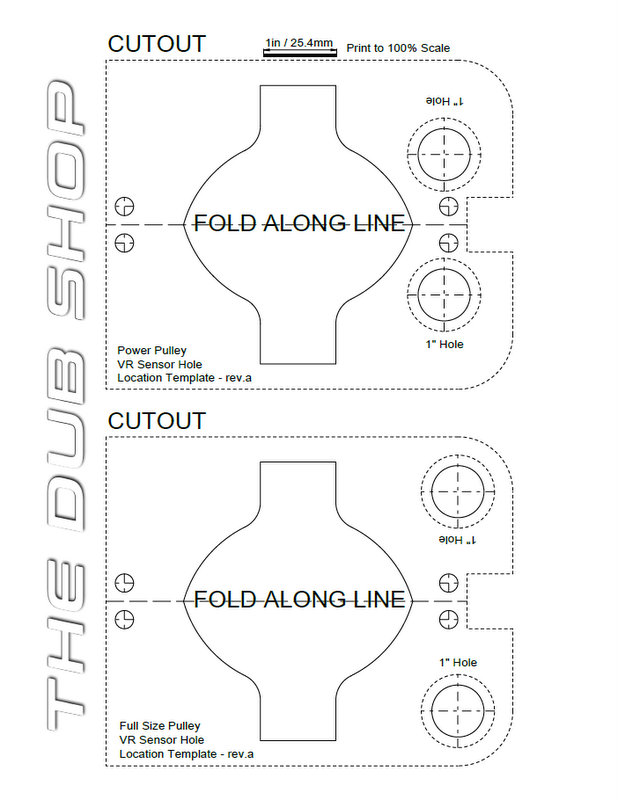
* Print this template * |
Mount sensor |
Print template |
|
|
Fold template in half |
|
|
Now tape front side |
Prepare for 1/8" pilot hole |
Pilot hole drilled |
|
Enlarge Pilot with hole-saw or Uni-bit |
Place tin to check fitment |
You will want to keep the hole slightly oversize to allow for sensor adjustment when the pulley is installed |


Indexing Your Trigger Wheel
With dozens of pulley options, multiple trigger wheel sizes and different crank sensor brackets, there are multiple options for installing the trigger wheel.
The 42.5 Degree angle referred to in the illustration above represents the missing tooth position BBDC (Before Bottom Dead Center). While viewing the pulley from the front this is at the 6-9 o'clock position and from the back the 3-6 o'clock position. My standard pulley is a CB Performance Santana Pulley. They are a high quality part with engraved timing marks. Pulleys with silk screened timing marks tend to rub off in a short period of time. 90 degrees is a standard sensor to missing tooth offset between ECU manufacturers. This puts the sensor at position "X" and the missing tooth 90 degrees ahead of it. The next tooth on the trigger wheel is the #1 tooth. This is known as the #1 tooth angle. Making my standard #1 tooth angle 80 degrees with a rising edge trigger.
42.5° BBDC - 6.5 - 7" Pulleys
35.5° BBDC - Power Pulleys
32.5° BBDC - Dry Sump or Bergmann Pulleys
Typical Sensor Gap - .030"
CB Performance products specifically the preferred #1 tooth angle is 70 degrees instead of 80. This moves the missing tooth 10 degrees closer to BDC on the pulley. So when using a CB Performance controller you will use the following missing tooth position.
32.5° BBDC - 6.5 - 7" Pulleys
25.5° BBDC - Power Pulleys
22.5° BBDC - Dry Sump or Bergmann Pulleys
Typical Sensor Gap - .030"
Sensor Wiring
MS2 Sensor WiringSensor / ECU
Red - VR+
Green - VR- Black - Shield |
MicrosquirtSensor / ECU
Red to VR-
Green to VR+ Black - Shield (can be left open/disconnected) 10k shunt resistor added across VR+/VR-
|
CB Performance Magna ProductsSensor / ECU
Red to VR- (Black)
Green to VR+ (Clear or White) Black - Shield (can be left open/disconnected) |
Fuel Tech 450/550Sensor / ECU Fuel Tech 600Sensor / ECU |
Software Settings
For Megasquirt 2, Megasquirt 3, and Microsquirt installations use these base ignition settings with my crank trigger packages:
#1 Tooth Angle 80°
Rising Edge
Once the installation is complete you will want to verify timing with a timing light. If the computer readout does not match the timing light adjust the #1 tooth angle to get the two to match. This is very important.